Lombardy
Client: Irideos Data Center Italia
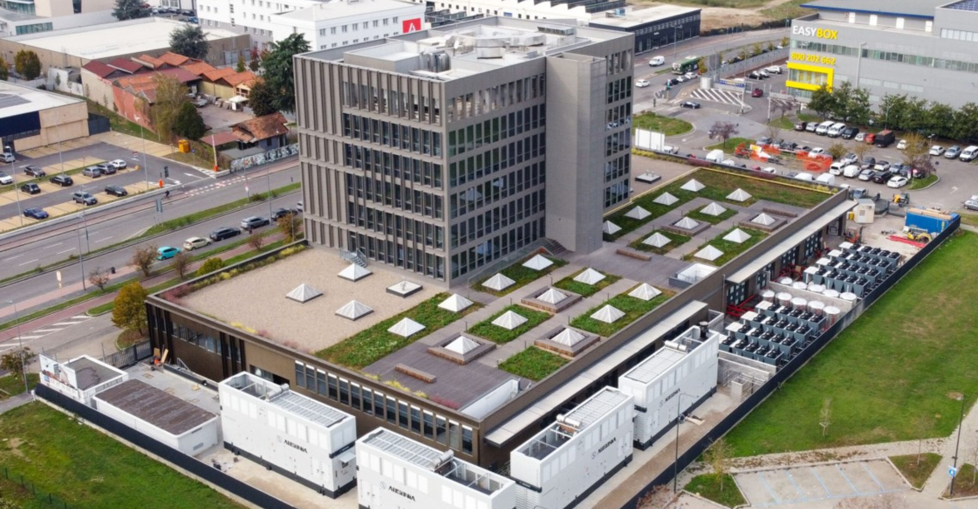
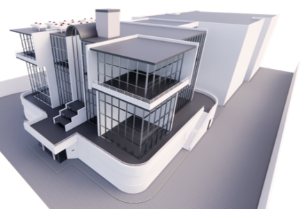
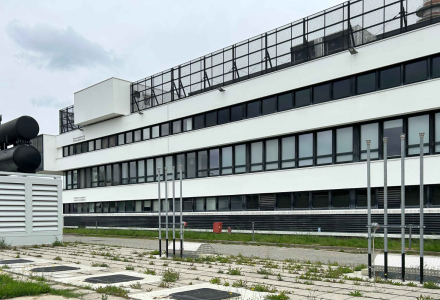
The project involved the construction of a new Data Center using the entire ground floor of the office building located at number 95, Via Bisceglie, in the eastern area of Milan.
The ground level serves as the base of an existing but recently completely renovated office tower, covering an area of approximately 3,500 square metres. Two outdoor areas of roughly 10.00 metres in depth extend along two sides of the building. In contrast, the access ramp to the basement, which is used as a garage, extends along the third sidewall.
The interior of the project area is industrial, with a load-bearing structure of precast reinforced concrete columns and beams and internal heights ranging from 4.50 to 6.00 metres.
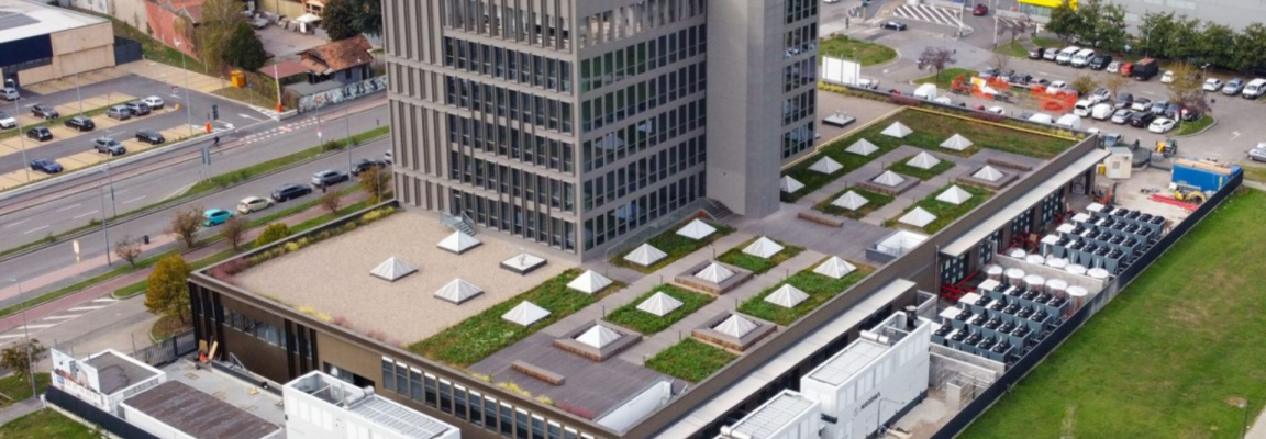
A roof garden extends across the roof of this floor, accessible to the occupants of the tower, with only a small area reserved and designated for the building installations and equipment. Two parking areas border the site to the North and West, with a dog park to the south. The main entrance is located on Via Bisceglie, on the East side of the building. There are three vehicle driveways: two providing East and North access to the external areas of the structure and one leading to the ramp of the underground car park.
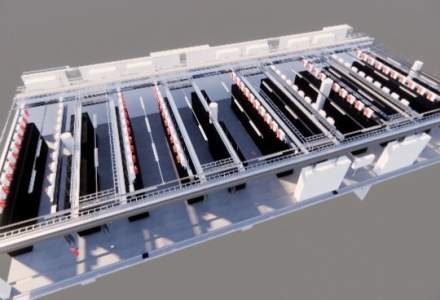
The Data Center covers the entire floor space of the ground level, surrounded by the technical rooms and spaces required for the operation of the control stations, which manage both the electrical and hydronic-aeraulic systems.
The management offices are in the main entrance area, featuring a split-level design. It consists of an access control and security hall, an office for Irideos staff, a control room and a break area. The double internal height also allowed a glazed meeting room on a newly constructed mezzanine.
The objective was to build a TIER I-compliant Data Center based on the ANSI/TIA 942 standard, providing double redundancy of the installation systems to guarantee high infrastructure reliability.
The generator sets, refrigeration units, adiabatic condensers and accumulation tanks have been installed in the outdoor area, with the addition of a new electrical cabin dedicated to the Data Center.
We designed the electrical and special installations: the medium-voltage electrical system with transformation to low voltage and its distribution, the primary and secondary switchboards connected to the electrical distribution structure, the standard and emergency lighting network, the FM system, earthing, generators, Uninterruptible Power Supplies (UPS), fire detection and automatic extinguishing, and the pre-configuration of the anti-intrusion and access control systems. The project also requires the monitoring and control of all the installations of the Data Center using a Building Management System (BMS) developed on multiple levels: the field, in which sensors (pumps, valves, and actuators) communicate and are activated by analogue and digital I/O cards; the acquisition of information from electrical panels; and the collection of data from machines.
Four independent branches were built. Each is equipped with a 3250 kA continuous operation Generator Set for Data Centers in compliance with ISO 8528, a 2500 kVA transformer and a system of distribution boards split between IT load and mechanical load. The IT load is protected by a 1250kVA modular UPS that can be expanded to 2500kVA. It is dedicated exclusively to critical loads. Whereas the mechanical loads are each supported by one 200 kVA UPS.
Each branch is also equipped with a 120 kW 2600 A at 48 Vdc power distribution unit. The overall load of the "four to make three" configuration, therefore, guarantees a total IT load of 3.20 MW. If one branch fails, all the loads equipped with a double power supply continue to be supplied by a double supply line drawn from the control station distribution boards. The four branches are designed to be completely independent and separate so that if one of the four branches experiences a problem, the entire system's functionality is unaffected.
There is also a fifth UPS to be switched on in the event of scheduled maintenance of one of the four central machinery installations in order to guarantee a dual path of continuity towards the critical load.
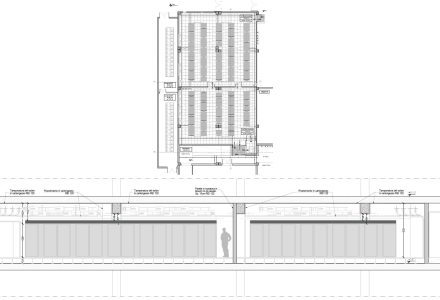
The mechanical systems have been designed to guarantee the proper functioning of the IT equipment installed in the rooms, to ensure maximum comfort for the people working in the office areas, to guarantee the fire safety of the IT equipment and the protection of staff, and to allow the reduction of energy consumption with the minimum objective of achieving an annual Power Usage Effectiveness (PUE) under 1.39.
The installations have also been engineered to meet the Class A1 requirements defined in the ASHRAE 'Thermal Guidelines for Data Processing Environments'. We designed the mechanical systems: liquid cooling (chilled and temperature-controlled water) and computer room ventilation (free cooling); automatic fire extinguishing; leak detection; UPS and battery room cooling; mechanical ventilation and cooling of transformer and switchboard rooms; temperature control and monitoring of the mechanical systems; air conditioning and ventilation of office spaces with VRV heat pumps; ancillary and complementary installations (water, plumbing, drainage, etc.).
A chilled water air conditioning system serves the data rooms with N+N redundancy and two separate generation and distribution circuits, each capable of supporting the total thermal load dissipated by the IT equipment and UPS units operating in the facilities. Eight air-cooled N+N configuration chillers were installed, four for each branch, working in standard "load-sharing" mode.
Internal distribution is provided by precision air conditioning units located in the data rooms, supplied by a loop system and fed by a primary and secondary distribution system.
For the distribution subsystem, the installation of 10 chilled water accumulation tanks (5 per circuit) with a capacity of 10,000 litres each was designed. The purpose is to provide a sufficient quantity of chilled water in order to guarantee the supply of the secondary circuits for at least 10 minutes in the event of a failure of the standard electrical network (continuous cooling).
The electrical rooms are served by precision direct expansion displacement air conditioning units with water condensation supplied by the same chilled water circuit.
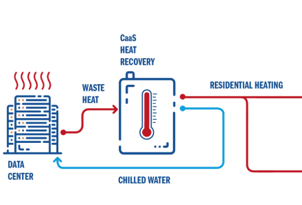
The system is also equipped with an indirect free cooling unit consisting of 2 adiabatic chillers designed to supply water at 18-26°C in order to optimise energy consumption: if the dry coolers are able to produce chilled water for the entire site, the loop is supplied solely by these elements. Otherwise, it is supplemented by the refrigerated water produced by the chillers.